i must admit that i am so pround of being part of this project. it takes us a lot of time and also cost almost $1000. but i have learned so much from doing this project. during the presentation a lecturer asked me what have i achieved from this project. i din't tell him much. but now i can say i have learned how to read a wiring diagram throughly. and i also have learned that how all the wires are wired on a vehicle. it used to be very complicated to me, but now it is so simple and so clear.
also the another thing we have learned is how to program a electronic device. before this i never imaged that it is so simple. we have learned that electromagnetic interference, but before it is just a conpect to me, coz i have never experienced with them. but now i have really had a good touch with it.
Wednesday, November 14, 2012
presentation day
time goes by so fast and our project also comes to a full stop. we are so excited to present our project to the class. it is the proof of our hard working and knowlege application. when we are doing the presentation we are asked a lot of questions by the lecturers which is not what we expected. may be we are not prepared enough or may be we don't have enough time to explain. but anyway, we are pround of the project we have done. and it will perform its destiney. this board is gonna used by Unitec to show a student how EFI system works without running the engine.
Wednesday, November 7, 2012
MAP sensor simuation
A MAP sensor is simply a vacuum gauge connected at the engine’s intake manifold and provides the ECU with engine load information. However, in our project a small DC motor is used to work as an engine to drive the distributor. Without the piston runs down inside a cylinder when the throttle is running at idle or at partly open position, vacuum cannot be produced for the MAP sensor. so a fixed value of 5 volts can only be sent to the ECU which is the atomosphere pressure voltage. so we decided to use a special electronic device to simulate the MAP sensor.

Except the for the PicAxe 08M chip, all the components can be bought as a kit at the price of about $ 10 from Surplustronics. The chip costs another extra $ 4. The kit includes a 22 K resistor, a 10 K resistor, a capacitor, programming unit and also a connector for programming.
without programming this unit is nothing more than a electronic device. this is the first time we acutually get into the touch with programming and it is not hard at all.
Wednesday, October 31, 2012
motor and throttle body synchronization unit
Since a small DC motor is used to work as an engine, a special designed DC motor and throttle body synchronization unit must be used. When the throttle is closed, the DC motor runs at idle at the speed of 800 rpm. With gradually opened throttle body, the DC motor speed increases correspondingly until reaches to top speed at 4000 rpm when the throttle is fully open. The following picture shows the DC motor and throttle body synchronization unit. It looks like just the same with the unit we have used for the MAP sensor, but the program and is totally different.
The programming of the DC motor and throttle body synchronization unit is the biggest problem we have ever encountered in the project as well as how to wire the unit into the EFI system. The following two pictures show the programs we wrote for the unit but the DC motor did not synchronize well with the throttle. We wrote over 10 programmes from the unit and tried again and again until it really works well.
Wednesday, October 24, 2012
Electromagnetic Interference
When electric devices are close or interconnected to each other, electromagnetic interference interacts among all these devices. As for our project, the primary source of interference is caused by the secondary ignition cables. When current stops and starts it creates a strong electromagnetic signal wave which interferes with other electronic systems such as crankshaft position sensor, camshaft position sensor and ignitor. The undesirable side-effect of the phenomenon of interference we encounter is that the louder electronic device operating noise and sometimes malfunctions of the electronic devices. and when we perform scope test, the interference is especially appeared on the waveforms
Wednesday, October 17, 2012
temperature sensor simulation

there are engine coolant temperature sensor and air temperature sensor included in this project. we thought of two ways to test these two sensors by using a heat gun. and also for the convenience of testing these two sensors, we decided to use a potential meter to simulate the temperature changing. As the potential meter is adjusted the resistance value changes correspondingly which changes the signal voltage to the ECU. howevery, the resistance of engine coolant temperatue sensor can goes from 10,000 ohms when it is cold and drops to a few hundred ohms when it is hot. the potential meter we used can only adjust from 1000 ohms to 3000 ohms, this is why when we use scope to test the sensor there is not much change.
Wednesday, September 26, 2012
LED for simulating injection pulse
one of the aggreed outcomes of this project is that we should include the fuel system. however when the atomized fuel meet with sparks from the spark plugs, dangerous can happen. under safety concideration, our superviser have agreed to cancle out the application of fuel pump. without the fuel pump runs fuel into the injectors, we have to use LED to simulate injection pulses.
 If an LED were connected directly across a 12 volt battery, it would light brightly, but only for a few seconds. Excessive current can destroy the P-N junction. The average LED requires only about 20-30 mA. So a resistor must be connected in series with every LED to control current flow. The method we have used to protect the LED is to connect a 470 ohm resistor in series with each LED. The resistor can be connected to either the anode or the cathode end.

Wednesday, September 19, 2012
project frame
now it comes to a new process. since we have tested all the components which are working correctly. the next task is to make a board to make it look nice and easily move around. again, if you have special skills, you will find out you can rely on them at any time and anywhere. Tony has the whole set of tools to make wooden projects. we calculated all the woods we are gonna need to make the demen

before comes to this point, Tony actually has spent a lot time to make all the mounts for the components. he is not only a good lecturer also a good carpenter. it takes so much time and patience. but he has been quite enjoying it. and all i can do is to hand over the tools he needs. there is nothing more i can do so far.
Wednesday, September 12, 2012
emergency protection
Fuses are used in circuits to protect the wiring from overheating and damage caused by excessive current flow as a result of a short circuit or other malfunction. Since this project is about to build an EFI system, so only limited fuses which are needed to protect the circuits. During the testing of the project we burned a few fuses. It is so wise we have built the fuse panel into the system.

and also all the wiring connection we used heat shrink tube to prevent moisture
Wednesday, September 5, 2012
nightmare: nothing happens
when we assembled the system to test if all the components were working correctly, there was no fuel and no spark. As we know most electronic fuel-injection computer systems use the pick-up coil or crank sensor pulse as the trigger for when to inject fuel from the injectors. If this signal were not present, no fuel would be injected. Because this pulse is also necessary to trigger the module to create a spark from the coil, it can be said ‘no fuel, no spark’ situation. So we spent hours on testing the distributor and wiring to find the problem. Fortunately, we found out that the distributor was not earthed. When a distributor in a vehicle, it is earthed to the engine body through the metal mounts. Since now it is mounted onto a wooden board, the distributor must be earthed to the battery negative.
Wednesday, August 22, 2012
wiring diagram explanation
until now, i guess i have enough knowledge to read wiring diagram after doing so many practice. so i think it is a good idea to sum up the way how i manage to read the wiring diagram for engine EFI system.
first of all, you have to find the engine information which normally can be found in the engine bay with a metal plate with engine information on it. or you can find the engine modle from the ECU which normally has the engine medle printed on it. once you have the information, then you can download the wiring diagram for the engine you choose to work on. the wiring diagram pakage includings all information you are gonna need. but also including the diagram for other engine modles, for example for the project we are doing, the wiring diagram pakage has information on left-hand-drive modles and aslo have the wiring diagram for 4E-FE ( for the project we only need 4A-FE). once you get right diagram you can continue to do the next step


first of all, you have to find the engine information which normally can be found in the engine bay with a metal plate with engine information on it. or you can find the engine modle from the ECU which normally has the engine medle printed on it. once you have the information, then you can download the wiring diagram for the engine you choose to work on. the wiring diagram pakage includings all information you are gonna need. but also including the diagram for other engine modles, for example for the project we are doing, the wiring diagram pakage has information on left-hand-drive modles and aslo have the wiring diagram for 4E-FE ( for the project we only need 4A-FE). once you get right diagram you can continue to do the next step

from the wiring diagram pakage wihch is for 4E-FE

from the wiring diagram pakage wihch is left-hand-drive

for righ-hand drive which is the right one for the project

for 4A-FE which is the right one for the project
if you are familiar with a map, then it is basically the same principle. all componnets are marked. since one paper can not show them all, you will notice they are seperated to different sections, put all these sections together you will have the whole picture. bear this in mind, one you find the power source which is normally the battery, then the conduct which is the wire, the last will be the componnet. all the wires in a car are the same with the wiring diagram. and aslo the location of the components are indicated.
Saturday, August 18, 2012
finally, wiring part comes to an end
Hooray, we have been working on the wiring part for a couple of weeks. now it finally comes to an end. i would like to show you how we make the work tidy and effective after the bad experience happened.
 since we don't need every function of the dashboard, we have taken out all the wires unnecessary. these are what left and they are taped to make job easy and tidy.

 as one of the most important components, the ECU has a lot of wires running into it. what you can see now is like only 1/3 of wiring. and also all the wires are taped and categorized.
to disconnect wires from either the ECU or the dashboard connector is really a patient job.
they have different design but have the same basic principal, now i'd love to show you what i found on the connector to dashboard
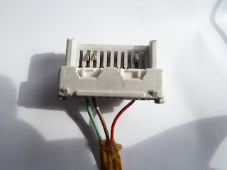 this is the d connector to the dashboard according to the wiring diagram, as you can see, most of the wires have been removed
 to remove the wires from the connector, a special thin long needle has to be used. there are two locking tabs can be only taken out towards the wire direction
 as the big tab removed out, the small one will just falling out without pushing by the needle
 here shows the small tab


to disconnect wires from either the ECU or the dashboard connector is really a patient job.
they have different design but have the same basic principal, now i'd love to show you what i found on the connector to dashboard


the wires are connected to the metal termianl to make contack with the metal bars on the dashboard. to take out the metal termial, the needle has to be used to push a locking pin underneath towards the bottom

some wires removed from the ECU connectors

some wires removed from the dashboard connectors
Saturday, August 4, 2012
wiring 4
This has been the fourth week of the wiring job, I thought we almost finished it. But the truth is as we go deep, we found more jobs we have to finish. When we took all the components and wiring harnesses out, we had to keep all the original wires. Since our project is to build the EFI system, there are a lot of them we won’t need. So now we have to clear all the wires which are not part of the project.
The worst thing ever is that when we are trying to clear the wires they are all tangled together.

Here is the picture shows how a big mess it is. Actually some wires on the combination meter and fuel pump are not showing in this picture, and also we have cleared some of it. We should have taped them to avoid them run into each other in the first place. Now we have to clean the mess.
The other thing is that the wiring diagram we had before is actually only part of it. When we came to the fuel pump and combination meters connection, we did not find any information at all. So we went to ask our supervisor to help us to get the whole wiring diagram.

The one we used since the beginning.

The one we get from our supervisor which is bigger displayed and all the information included.
With the help of the new wiring diagram, we start to disconnect all the wires which are not part of it. I have to tell the truth that I have learned so much from this project. how to read a wire diagram, they are so well designed for understanding. what is the different between the real wiring and the wire diagram. How to make a profession wire connection. How the connectors work.


Here are some pictures we took after we disconnect all the unnecessary wires and taped the wires. Really good job.
Saturday, July 21, 2012
wiring 3
we wanted to basically run the project before we start the next semester, so we worked on the weekends. on the thrid day of wiring, we had most of the sensors and components connected to ECU. but there are also heaps of wires we have to clean out since they have nothing to do with EFI system. and also there are a few sensors we haven't found the connection yet. some of the wires are too short when we took them off the car, so we made some new connections.
since the wiring diagram is slightly different with the one we are doing, so we have to locate them by checking the wire colors among hundreds of them.
since the wiring diagram is slightly different with the one we are doing, so we have to locate them by checking the wire colors among hundreds of them.
Wednesday, July 18, 2012
wiring 2
the next day, we continued to work on the wiring, coz it would never be so easy to finish. i even come into a conclusion, vehicle wiring may be the hardiest part of the design. but after the first day, i clearly got more confidence. now i know what should i do to make my job easier. we still left few components and wiring harness on the car such as fuel pump and cluster wiring. i know it is a good opportunity for me to understand how the wirings are designed in a car, instead of simply cutting the fuel pump wiring, i removed all the seats and cut the carpets even took apart the ceillling, i was so exciting i found a lot of mechanism designs are so simple but they are also very high effective. after i had what i wanted, i moved to the project. i jusft found how luck i am for working on this project. it just helps you so much to practially understand how all the sensors working togethe with the ECU.
Wednesday, June 13, 2012
headache
straight to the point, when our project comes to the wiring, i swear it really gives me a big headache. when we took it off the car, we had to cut most of them, there was no way which we could keep them completely. so when we put them on the table, all the components, the ECU and the wire harnesses are seperately in a really big mess. even some of them are not part of our project, but you just have to take them together as well. there is no way you can work them out without a wiring diagram. so we downloaded all the wiring diagram related to EFI system. i have learned the theory before, but when all the wires, ECU and componnets put on the table, you just have no idea how struggle you can be. after consulting with Tony, we determined to start from clearing all the wires first, coz they tangled together. it would be very wise if we labled them and taped them in order when we took them off the car. but now we have to face the fact which we did not do so. we started from the wirs on the ECU, we put them one by one and taped them so it won't tangle with others again. honestly, i even read the diagram wrong when i first tried to work on it. after all the wires are labled and cleaned, we continued to located all the connectors to each sensors.
seriously, even when i am doing all calculations i nerve got headache, but this just keeps me struggling.
seriously, even when i am doing all calculations i nerve got headache, but this just keeps me struggling.
Wednesday, June 6, 2012
process
we basically have all the requirements to start our project. today, we put our EFI components onto a board. Tony and i think it will be a good idear, if we can make the whole system works first, then next semester, we will improve it and make it better. under the concern of friendly evirionmentally and sustainability, we think we will use some kind of fluid which is not flammable and no corrosion ability to injectors to simulate the gasoline spray patterns in the injectors.since we also need to simulate the spark in the spark plug, this is why we can not use gas. as all the componnets in a car, you may never notice how imporant it is of the design of the whole sysem such as how to connect them in a logical way. but once you have to put them on a limited board the location of the many components are critical to the whole project design. before we actually fix them onto the board, we have to swap all the parts all around to get their perfect location.
Wednesday, May 30, 2012
wire diagram
Hooray, we have finnaly put each components onto the wood board. when we took them out off a vehicle, we had to cut their connction wires to make job easy. as a result, now we have to re-wire them to make them work. Thanks to Tony, he has got all the wire diagrams which we need. and aslo we both agreed to use anti-freeze to simulate the fuel running in the fuel system which will avoid any cathing a fire accident. but i am still a little bit worried about that if we can successfully get the fuel to the injectors and have desired spay patterns.
Wednesday, May 16, 2012
catch up
lucky, we have the chance to look at a EFI circuit board which is very professionally desgined. it really gives us a idea how to improve our project. After talking to our supervisor, we are happy to design our own EFI circuit as a extra part of our project which we think that will greatly help the purpose of education. if we can come up with a very nice finished project, we will have the chance to sell it to some educational institute. as a memeber of our team, Tiitii had a big surgery which is required to take this semester off by the doctor. so now only Tony and i have to fnish the project. we know it will be a chanllenge, but even though we will face it.
Wednesday, May 9, 2012
problems with our project
in our TC project, we have solved the issue which is how to control the distributor. we came up with the idear to use a DC speed motor to simulate the engine revolution. however, how to simulator the engine vacuum will be a real big problem. i did some researches which like using a Ford vucuum pump used in diesel engine. and aslo we can use a hand-operated vacuum pump in which we can exactly control the vacuum produced in the petrol engine. the other problem is that Tony thinks we can use a hammer to simulate the engine knock event. but as far as i know, the engine knock sensor actually only works in a specific frequency. so it won't pick up the unrelated noise. and in fact i saw some one failed to simulate the engine knock event by hit the engine with a hammer.
Wednesday, April 25, 2012
the contract
Fortulately, our supervisor made a agreement with us and did some changes to our original plan. here followes the contract in which we are gonna to finished all the agreements.
· Put all 4A-FE engine electronic parts on a designed demonstration board.
· Use a small DC motor to drive distributor rotor.
· The speed of the DC motor is simulated to the camshaft speed which can be controlled by a speed controller.
· The speed controller gets input from TPS to synchronize accelerator and distributor.
· Use spark plugs or spark plug testers to show ignition sparks.
· Use a fuel tank with fuel pump to supply pressured fuel or special liquid to rail with injectors.
· ECU gets all inputs like real engine and controls 4 injectors to spray fuel to transparent plastic tubes which are connected back to fuel tank.
· Map sensor may not be simulated.
· ECT can be simulated by a POT or can be heated up by heat gun.
· IAT can have the same design with ECT.
· Knock sensor signal can be simulated by a hammer.
· O2 sensor may not be simulated.
· Idle air control valve may not be simulated.
· Cam and crank sensors are combined with distributor and can be tested by scope.
· Use 12V battery to drive DC motor, fuel pump and power ECU / injectors / ignition
· Use a key set to simulate ignition switch.
· Diagnostic connector can be used with scan tool.
· A designed diagnostic port with diagrammed testing terminals can be easy to use with scope.
· A user manual will be available. All sensors and actuators waveforms included.
· Easy to be moved around and design for education.
· Simulate to real engine. Not only spark frequency and injection formation can be seen on board, they can be changed when accelerating, decelerating and idle.
Wednesday, March 21, 2012
project process now is to a new level
before we got a final display board from Unitec, we determined to buy a one by ourselves first in order to get better design. After project calss, we again together went to Tony's workshop. Tiitii's task was to put all the EFI components nicely and logically on the board which we just bought from Bunnies warehouse. then make all the measurements we need for our final board.
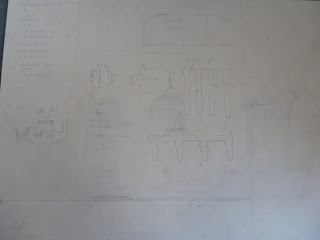 this is the picture we took after Tiitii finished the drawing, we will basically design our project on this blueprint.
all i have to do was to solder the speed motor control unit which i have nerver done that before. the lucky thing is that Tony knows it and i asked him some technical questions then got started. it was fun at the beginning, however it really piss you off after a few try. it took me five hours to finally get it done. but i don't know if it will work, but we will know once we use it.

 the printed borad for speed motor control before i work on it

 after i finised the soldering, ugly is not it?
about Tiitii's board design, we have to discuss all the time to decide which way to put the components is the best. after we came to a final decision, we took some pictures as a part of our project. next week is the time to sign the contract with our supervise. once we get his satisfaction, we can really start to do our project. our project.

we used one of the sides of the board to arrange the components so we can decide the best way to put them.

all i have to do was to solder the speed motor control unit which i have nerver done that before. the lucky thing is that Tony knows it and i asked him some technical questions then got started. it was fun at the beginning, however it really piss you off after a few try. it took me five hours to finally get it done. but i don't know if it will work, but we will know once we use it.


we used one of the sides of the board to arrange the components so we can decide the best way to put them.
Wednesday, March 14, 2012
meeting with our supervisor
to build the speaker motor control unit, i went to jaycar. so lucky that they have the unit in a kit. all i have to do is carefully to read the instruciotn then build the unit step by step. not very hard, but do take me a while to understand how it works. the only thing left out is that i have to solder them together. that will be done in Tony's workshop.
time goes by fast, the second class on TP came up. when every group is talking to the supervisor about their ideas, we actually have started to build our project. after class we had a meeting with Prahbat. he wants us to finish this project very professionally. that will be really a challenge to us all. and in the following week we have to show him our process on:
1: the project layout plan
2: wiring diagram
3:lists of parts
4: size of the board
we went to Tony's workshop again to put all exsiting components in a logical way and decided to buy a board first then try to make it work
Wednesday, March 7, 2012
very exciting
i have heard of that technology project will be a hard ass. luckly enough, on the very first class on TP, Tony came up with a brilliant project and offers Tiitii and me to be partners of his. what a honor. that would really save us a lot of time and we can start the project right away. with Tony's knowledge, i believe that we can push our project to a very high level.
after class, we had a meeting among three of us. the project that Tony has is to build a EFI system. we have to clearly demonstrate the fuel formation and spark. without working with the eninge, how to simulate vacuum would be a real challenge to us. i did some research on how to build our own vacuum pump and came up with two ideas:
1; use a fridge compressor unit and other componets to build one
2: buy a electric vacuum pump used on Ford diesel engine
the first one is obvious a little bit complex and hard to control
the last one we can simply control it by using a potentiometer to work with
but how it goes, will depend on the process we are making on the project
to further throughly understand the project, Tiitii and i went to Tony's work shop. he has disassembled a whole EFI system from a old TOYOTA COROLLA. we will put these components onto a white board to make them work. a speaker control motor would be used to play the part of the engine.
to share the job, Tiitii will make a drawing for the board
and my job is to build a control unit to control the motor speed
Subscribe to:
Comments (Atom)