Wednesday, August 22, 2012

wiring diagram explanation

until now, i guess i have enough knowledge to read wiring diagram after doing so many practice. so i think it is a good idea to sum up the way how i manage to read the wiring diagram for engine EFI system.
first of all, you have to find the engine information which normally can be found in the engine bay with a metal plate with engine information on it. or you can find the engine modle from the ECU which normally has the engine medle printed on it. once you have the information, then you can download the wiring diagram for the engine you choose to work on. the wiring diagram pakage includings all information you are gonna need. but also including the diagram for other engine modles, for example for the project we are doing, the wiring diagram pakage has information on left-hand-drive modles and aslo have the wiring diagram for 4E-FE ( for the project we only need 4A-FE). once you get right diagram you can continue to do the next step
from the  wiring diagram pakage wihch is for 4E-FE

from the  wiring diagram pakage wihch is left-hand-drive

for righ-hand drive which is the right one for the project

for 4A-FE which is the right one for the project
if you are familiar with a map, then it is basically the same principle.  all componnets are marked. since one paper can not show them all, you will notice they are seperated to different sections, put all these sections together you will have the whole picture. bear this in mind, one you find the power source which is normally the battery, then the conduct which is the wire, the last will be the componnet. all the wires in a car are  the same with the wiring diagram. and aslo the location of the components are indicated. 


Saturday, August 18, 2012

finally, wiring part comes to an end

Hooray, we have been working on the wiring part for a couple of weeks. now it finally comes to an end. i would like to show you how we make the work tidy and effective after the bad experience happened.
 since we don't need every function of the dashboard, we have taken out all the wires unnecessary. these are what left and they are taped to make job easy and tidy.

as one of the most important components, the ECU has a lot of wires running into it. what you can see now is like only 1/3 of wiring. and also all the wires are taped and categorized.

to disconnect wires from either the ECU or the dashboard connector is really a patient job.
they have different design but have the same basic principal, now i'd love to show you what i found on the connector to dashboard
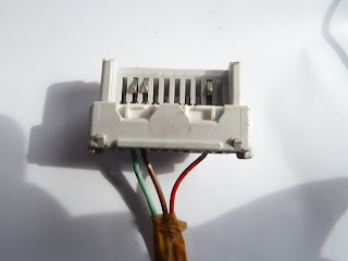
 this is the d connector to the dashboard according to the wiring diagram,  as you can see, most of the wires have been removed
 to remove the wires from the connector, a special thin long needle has to be used. there are two locking tabs can be only taken out towards the wire direction
 as the big tab removed out, the small one will just falling out without pushing by the needle
 here shows the small tab


the wires are connected to the metal termianl to make contack with the metal bars on the dashboard. to take out the metal termial, the needle has to be used to push a locking pin underneath towards the bottom 
some wires removed from the ECU connectors 

some wires removed from the dashboard connectors

Saturday, August 4, 2012

wiring 4

This has been the fourth week of the wiring job, I thought we almost finished it. But the truth is as we go deep, we found more jobs we have to finish. When we took all the components and wiring harnesses out, we had to keep all the original wires. Since our project is to build the EFI system, there are a lot of them we won’t need. So now we have to clear all the wires which are not part of the project.

The worst thing ever is that when we are trying to clear the wires they are all tangled together.

Here is the picture shows how a big mess it is. Actually some wires on the combination meter and fuel pump are not showing in this picture, and also we have cleared some of it. We should have taped them to avoid them run into each other in the first place. Now we have to clean the mess.
The other thing is that the wiring diagram we had before is actually only part of it. When we came to the fuel pump and combination meters connection, we did not find any information at all. So we went to ask our supervisor to help us to get the whole wiring diagram.

                                                                The one we used since the beginning.

The one we get from our supervisor which is bigger displayed and all the information included.
With the help of the new wiring diagram, we start to disconnect all the wires which are not part of it. I have to tell the truth that I have learned so much from this project. how to read a wire diagram, they are so well designed for understanding. what is the different between the real wiring and the wire diagram. How to make a profession wire connection. How the connectors work.

Here are some pictures we took after we disconnect all the unnecessary wires and taped the wires. Really good job.